First, start off by identifying connectors...this picture helps a lot:
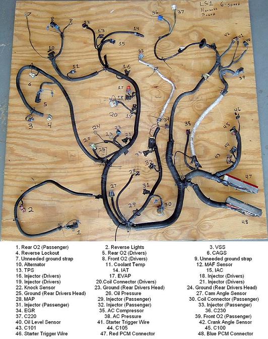
This harness is also from a 6 speed F-body, but since you'll be getting rid of all the A/T stuff anyway, you just have to pay attention to what's in here and trash the stuff it's missing. Decide what you want to keep as far as emissions, A/C, etc... go, and then label each connector on your harness with some painters tape and a marker. I can't tell you what to keep and what not to keep, it's all basically up to you.
Next start tearing apart the harness, start at the end of the harness farthest away from the PCM connectors, removing the connectors you chose as you go along and pulling the wires for them apart from the harness. I've found that even though it's still a big mess towards the end, there isn't a much easier way to do it. There's a few wires in there that go to splice points inside the harness, for these just cut the wire at the splice and tape over it to avoid shorting. Follow the wires all the way to where they end at the PCM. Use a pinout diagram to verify the wires and make sure you didn't screw up, then take the red/blue plastic ends off and push the wires through the front of the connector, there aren't any tabs holding them in, they just push out.
The next step is to thin out the 5 body connectors: C100, C101, C105, C220, and C230. C220 and C230 are in-dash connectors for gauges and whatnot, the other 3 are underhood connections. The vast majority of the wires to these come from the PCM itself. The others come from sensors or are power/ground wires. The easy way to do this is to first eliminate the wires you don't need from each connector.
To give you a basic rundown of things, all you need to look for is the following:
MIL illumination going to C230-B
Serial data line going to C230-K
Generator warning light going to C220-A
Oil PSI going to C220-B
ground in going to C220-E
IGN B+ hot in run/start going to C100-A&G, C101-B&E, and C105-G (all these wires are pink)
Fuel pump relay power to C101-D
B+ constant power for computer going to C101-G
ground in going to C101-H
Remove the white tach signal wire from C105-G, then lengthen and run it to C220 or C230
Everything else is basically trash, use a needle to push the pigtails out of the connectors and ditch what you don't need. Take the ones you'll be needing and group them into two connectors, one for the C10X group and one for the C2X0 group. From here all you have to do is buy the mating connector for the ones you used and splice into the Porsche harness with them, and viola!
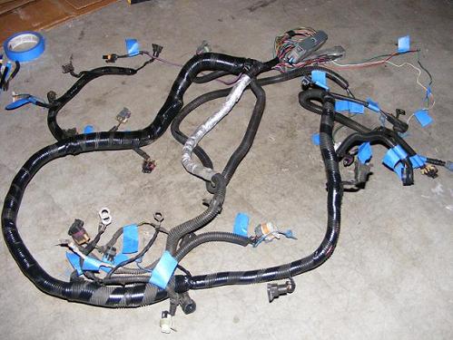
Once you've got your connections finished, electrical tape the harness back into shape and put the split loom back on (which is a royal PITA, btw), then electrical tape over the split loom to hold it together. When you're finished you should have a factory looking harness, but with about half the stuff as the original. If you did it right, there should be no loose ends unless you didn't want to lengthen the one tach wire. I had 3: tach, fuel pump, and a VSS wire since I chopped it for relocation, but I'll sort them out another day.
Here's the finished product:
and all the stuff I pulled out of it:

Comments (0)
You don't have permission to comment on this page.